NNH4-45A-HG-R3B
12-port Next Generation PerforMax™ sector antenna, 4x 698-896 MHz and 8x 1695-2200 MHz, 45° HPBW, 3X RETs and 3x SBTs
Features and Benefits
- Antenna optimized for higher gain with improved radiation efficiency
- Powered by Andrew’s SEED® technology (Sustainable Energy Efficient Design)
- Narrow beamwidth capacity antenna for higher level of densification and enhanced data throughput
- Internal SBT on low and mid band allow remote RET control from the radio over the RF jumper cable
- Separate RS-485 RET input/output for low and mid band
- Interleaved dipole technology providing for attractive, low wind load mechanical package
- Best in class PIM immunity
Specifications
General Specifications
| Antenna Type | Sector |
| Band | Multiband |
| Color | Light Gray (RAL 7035) |
| Grounding Type | RF connector inner conductor and body grounded to reflector and mounting bracket |
| Performance Note | Outdoor usage |
| Radome Material | Fiberglass, UV resistant |
| Radiator Material | Low loss circuit board |
| Reflector Material | Aluminum |
| RF Connector Interface | 4.3-10 Female |
| RF Connector Location | Bottom |
| RF Connector Quantity, mid band | 8 |
| RF Connector Quantity, low band | 4 |
| RF Connector Quantity, total | 12 |
Remote Electrical Tilt (RET) Information
| RET Hardware | CommRET v2 |
| RET Interface | 8-pin DIN Female | 8-pin DIN Male |
| RET Interface, quantity | 3 female | 3 male |
| Input Voltage | 10–30 Vdc |
| Internal Bias Tee | Port 1 | Port 5 | Port 9 |
| Internal RET | Low band (1) | Mid band (2) |
| Power Consumption, active state, maximum | 10 W |
| Power Consumption, idle state, maximum | 2 W |
| Protocol | 3GPP/AISG 2.0 |
Dimensions
| Width | 749 mm | 29.488 in |
| Depth | 197 mm | 7.756 in |
| Length | 1030 mm | 40.551 in |
| Net Weight, antenna only | 34 kg | 74.957 lb |
Array Layout
| Click on image to enlarge. |

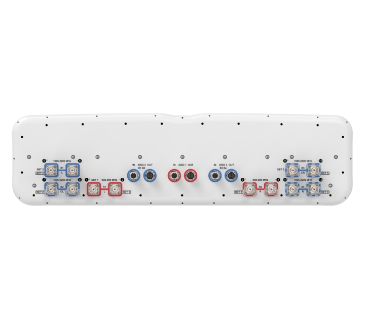
Port Configuration
| Click on image to enlarge. |

Electrical Specifications
| Impedance | 50 ohm |
| Operating Frequency Band | 698 – 896 MHz | 1695 – 2200 MHz |
| Polarization | ±45° |
| Total Input Power, maximum | 900 W @ 50 °C |
Electrical Specifications
| R1-R2 | R1-R2 | B1-B4 | B1-B4 | B1-B4 | |
| Frequency Band, MHz | 698–806 | 806–896 | 1695–1880 | 1850–1990 | 1920–2200 |
| RF Port | 1-4 | 1-4 | 5-12 | 5-12 | 5-12 |
| Gain, dBi | 13.9 | 14.3 | 17.4 | 18.0 | 18.6 |
| Beamwidth, Horizontal, degrees | 48 | 42 | 50 | 48 | 45 |
| Beamwidth, Vertical, degrees | 22.1 | 20.1 | 8.9 | 8.3 | 8 |
| Beam Tilt, degrees | 2–18 | 2–18 | 2–12 | 2–12 | 2–12 |
| USLS (First Lobe), dB | 15 | 15 | 15 | 15 | 15 |
| Front-to-Back Ratio at 180°, dB | 31 | 30 | 33 | 33 | 33 |
| Isolation, Cross Polarization, dB | 25 | 25 | 25 | 25 | 25 |
| VSWR | Return loss, dB | 1.5 | 14.0 | 1.5 | 14.0 | 1.5 | 14.0 | 1.5 | 14.0 | 1.5 | 14.0 |
| PIM, 3rd Order, 2 x 20 W, dBc | -153 | -153 | -153 | -153 | -153 |
| Input Power per Port at 50°C, maximum, watts | 300 | 300 | 250 | 250 | 250 |
Mechanical Specifications
| Wind Loading @ Velocity, frontal | 1,000.0 N @ 150 km/h (224.8 lbf @ 150 km/h) |
| Wind Loading @ Velocity, lateral | 95.0 N @ 150 km/h (21.4 lbf @ 150 km/h) |
| Wind Loading @ Velocity, rear | 1,000.0 N @ 150 km/h (224.8 lbf @ 150 km/h) |
| Wind Speed, maximum | 241 km/h (150 mph) |
Packaging and Weights
| Width, packed | 910 mm | 35.827 in |
| Depth, packed | 368 mm | 14.488 in |
| Length, packed | 1266 mm | 49.843 in |
| Weight, gross | 49.2 kg | 108.467 lb |
Regulatory Compliance/Certifications
| Agency | Classification |
| UK-ROHS | Compliant |
General Specifications
| Antenna Type | Sector |
| Band | Multiband |
| Color | Light Gray (RAL 7035) |
| Grounding Type | RF connector inner conductor and body grounded to reflector and mounting bracket |
| Performance Note | Outdoor usage |
| Radome Material | Fiberglass, UV resistant |
| Radiator Material | Low loss circuit board |
| Reflector Material | Aluminum |
| RF Connector Interface | 4.3-10 Female |
| RF Connector Location | Bottom |
| RF Connector Quantity, mid band | 8 |
| RF Connector Quantity, low band | 4 |
| RF Connector Quantity, total | 12 |
Remote Electrical Tilt (RET) Information
| RET Hardware | CommRET v2 |
| RET Interface | 8-pin DIN Female | 8-pin DIN Male |
| RET Interface, quantity | 3 female | 3 male |
| Input Voltage | 10–30 Vdc |
| Internal Bias Tee | Port 1 | Port 5 | Port 9 |
| Internal RET | Low band (1) | Mid band (2) |
| Power Consumption, active state, maximum | 10 W |
| Power Consumption, idle state, maximum | 2 W |
| Protocol | 3GPP/AISG 2.0 |
Dimensions
| Width | 749 mm | 29.488 in |
| Depth | 197 mm | 7.756 in |
| Length | 1030 mm | 40.551 in |
| Net Weight, antenna only | 34 kg | 74.957 lb |
Electrical Specifications
| Impedance | 50 ohm |
| Operating Frequency Band | 698 – 896 MHz | 1695 – 2200 MHz |
| Polarization | ±45° |
| Total Input Power, maximum | 900 W @ 50 °C |
Electrical Specifications
| R1-R2 | R1-R2 | B1-B4 | B1-B4 | B1-B4 | |
| Frequency Band, MHz | 698–806 | 806–896 | 1695–1880 | 1850–1990 | 1920–2200 |
| RF Port | 1-4 | 1-4 | 5-12 | 5-12 | 5-12 |
| Gain, dBi | 13.9 | 14.3 | 17.4 | 18.0 | 18.6 |
| Beamwidth, Horizontal, degrees | 48 | 42 | 50 | 48 | 45 |
| Beamwidth, Vertical, degrees | 22.1 | 20.1 | 8.9 | 8.3 | 8 |
| Beam Tilt, degrees | 2–18 | 2–18 | 2–12 | 2–12 | 2–12 |
| USLS (First Lobe), dB | 15 | 15 | 15 | 15 | 15 |
| Front-to-Back Ratio at 180°, dB | 31 | 30 | 33 | 33 | 33 |
| Isolation, Cross Polarization, dB | 25 | 25 | 25 | 25 | 25 |
| VSWR | Return loss, dB | 1.5 | 14.0 | 1.5 | 14.0 | 1.5 | 14.0 | 1.5 | 14.0 | 1.5 | 14.0 |
| PIM, 3rd Order, 2 x 20 W, dBc | -153 | -153 | -153 | -153 | -153 |
| Input Power per Port at 50°C, maximum, watts | 300 | 300 | 250 | 250 | 250 |
Mechanical Specifications
| Wind Loading @ Velocity, frontal | 1,000.0 N @ 150 km/h (224.8 lbf @ 150 km/h) |
| Wind Loading @ Velocity, lateral | 95.0 N @ 150 km/h (21.4 lbf @ 150 km/h) |
| Wind Loading @ Velocity, rear | 1,000.0 N @ 150 km/h (224.8 lbf @ 150 km/h) |
| Wind Speed, maximum | 241 km/h (150 mph) |
Packaging and Weights
| Width, packed | 910 mm | 35.827 in |
| Depth, packed | 368 mm | 14.488 in |
| Length, packed | 1266 mm | 49.843 in |
| Weight, gross | 49.2 kg | 108.467 lb |
| Click on image to enlarge. |
| Click on image to enlarge. |
Regulatory Compliance/Certifications
| Agency | Classification |
| UK-ROHS | Compliant |
Documentation & Downloads
Assembly Drawing
Product Specification
Assembly Drawing
Product Compliance Documentation
Product Specification
Other Ways to Browse
